August 14, 2007
Intercooler Specs
The intercooler core I chose was the Spearco 2-182. The charge area is 3.5" x 15.6" (54.6 in^2) and the ambient air side is 15.6" x 20" (312 in^2) and is rated at 1500 cfm at a 1.5 psi pressure drop. I fabricated sheetmetal plenums on either side with a 3" inlet and outlet.
I'm waiting for Turbonetics/Spearco to email the intercooler flow chart. (8/14/07)
Posted by Z28tt at 9:14 AM
June 5, 2007
Mufflers?!!
I must be getting old (over the hill, aka 30 years old, as a friend of mine says!), since I think the Camaro is a bit too loud (that, and LimeRock has a very strict good neighbor policy at 83 dBa). I picked the Dynomax UltraFlow welded muffler - part #17517. It's a 3.5" center in/out with a 4.5"x9" oval canister, 14" long. The sound is rated "Sport", so it shouldn't be as obnoxious as the bullet mufflers that have a "Race" rating. It flows 2200+ cfm (probably maxed out Dynomax's flow meter gauge, they use 20.3" of water for the pressure), and is recommended for 1000 loss-free horsepower. It's on page 187 of their catalog at http://www.dynomax.com/ecat/pdf/TENNECO_DYNOMAX.pdf.
Posted by Z28tt at 12:48 PM
March 26, 2007
Swap Meet Water Pump
At the Thompson Speedway swap meet last fall, I picked up a Stewart 22203 water pump.
Chevrolet Small Block
Short Stage 2 - 22203
* Chevrolet Small Block - Short
* 1955-68 Passenger Cars
* 1955-72 Light Trucks
* 1955-70 Corvette
* 5.625" Length
* 3/4" Bearing
* 3/4" Shaft
* Special Severe Duty Pump
* High Flow Pump
* Cast Aluminum Finish
* High flow impeller
* Equal flow to left and right cylinder heads
* High flow and pressure
* 356-T6 heat treated aluminum specially ribbed casting
* Precision ground fan hub with dual bolt pattern
* Zinc-plated rear cover and bolts
* Extra rigid cam stop with 3/8" adjustment screw for small block models
* Two 1/2" NPT auxiliary inlets
* Extra material on small block Chevrolet models for installing external lines to center of the cylinder heads
Posted by Z28tt at 4:36 PM
March 8, 2007
Turbocharger Specs & Calcs
Turbonetics T04E
O Trim Turbine Wheel (appx 61.7 Trim)
EXDUCER DIA.: 2.296" (58.3mm)
MAJOR DIA.: 2.922" (74.2mm)
40 Trim Compressor Wheel
INDUCER DIA.: 1.870" (47.5mm)
MAJOR DIA.: 2.950" (74.9mm)
INLET DIA.: 3.000" (76.2mm)
OUTLET DIA.: 2.000" (50.8mm)
TrimCompressor = (Inducer Dia) ^2 / (Major Dia) ^2 * (100)
TrimTurbine = (Exducer Dia) ^2 / (Major Dia) ^2 * (100)
Larger trim supports more airflow
.58 A/R
Map:
To read the chart, first calculate the airflow.
Cubic Inch Displacement (CID) = 399
Volumetric Efficiency (VolE) = 90% (estimated)
RPM = 6000
Boost Pressure = 5 psig, 14.7 psig, 20 psig
CFM = RPM * CID * VolE / (1728 in^3 per ft * 2 revolutions per cycle)
CFM = 6000*399*.90/3456 = 623 cfm
Since the Turbonetics maps are in their corrected lb/min, we have to convert CFM to lb/min, and then apply a correction to match their inlet temperature & pressure.
Ideal Gas Law is PV=nRT, or switched around to lbs is n (lbs/min) = PV/(RT)
P is Absolute Pressure, psia, so add 14.7 to your boost pressure
5 + 14.7 = 19.7 psia
V is Volume, or CFM = 623 cfm
R=10.73 (universal gas constant for air in these calcs)
T=Temp, in Rankine (add 460 to DegF), 110 degF + 460 = 570 degR
19.7 psia * 623 cfm * 29 / (10.73 * 570 degR) = 58.2 lb/min
Since we have 2 turbos, also divide by two.
Lb/min@5psi = 29.1 lb/min
Lb/min@14.7psi = 86.8 / 2 = 43.4 lb/min
Pressure ratio = (boost + atmosphere) / atmosphere
PR5 = (5+14.7)/14.7 = 1.34
PR14.7 = 2
Draw a line from the lb/min on the X axis going up, and the pressure ratio on the Y axis going across. Where they intersect is the turbochargers efficiency (and speed). At 5 psi, you have a PR of 1.34, and 29.1 lb/min. This is to the lower right of the graph, and not very efficient (on the 69,800 rpm line). At 14.7 psi boost, you are at a PR of 2 and 43.4 lb/min, well to the right of the map. This shows that the engine is producing much more flow than the compressor can pump, so it won't be very efficient. Back when these turbos were chosen, they were designed around 5500 rpm 305 (436 cfm) and 8 psi boost (PR 1.55), which has 22.7 lb/min airflow, and would be right around 72% efficiency. Upgrading to a 60 Trim compressor would put me at 70% at 5 psi, and 73% at 14.7 psi boost.
What I need to do for now is short shift it. By reducing the RPM by a third to 4000, the airflow also gets cut by a third. 5psi=19.5 lb/min & 65% efficiency and 14.7psi=29 lb/min & 73% efficiency.
Posted by Z28tt at 5:29 PM
Video & sound from the dyno runs
I spent 4 hours cutting down 20 minutes of footage to 4 minutes last night. It's best if you watch google videos in the original size (little icon on the bottom right of the movie window).
http://video.google.com/videoplay?docid=4282173294346413965&hl=en
This is just the first run at 4 psi and some steady state tuning off the street - you can really hear when the dyno loads the engine near the end... I'll get the other runs done tonight when we turn up the boost.
I stripped the sound out of the dyno video for a 750 kb mp3 clip:
http://www.skulte.com/video/bristoldyno_sound.mp3
Be sure to put this in your ipod, and crank up the stereo on the daily driver!
Full engine details at http://www.skulte.com/z28tt/archives/2004/05/engine_specs.html
Posted by Z28tt at 12:37 PM
March 1, 2007
17 more dyno runs!
Jonathan at BristolDyno.com was great, and really helped us get many runs in just 3 hours tonight. The directory with all the Dynojet runs (and a free viewer from dynojets website) is at:
http://www.bristoldyno.com/vehicles/Chevrolet/Camaro/Skulte_Andris/
1st run was right as-is off the street - mostly under 4 psi - 455 hp & 445 tq
Not logged, but we did some steady state with the dyno brake (Dynojet 240 w/ a brake). I was overpowering it at low rpm, no boost, and it would only hold it for about a minute before the brake would overheat & start slipping. I think there's some good video of my cast iron manifolds glowing cherry red! (Got to get the EGT's in there) I'd like to play more with the steady state & ignition timing next time, but it's not just not beefy enough for more than a minute or two at a time it seems.
2nd was a bit warmer, no changes - 459hp/454 tq
3rd run I added 2 degrees of timing - 33 at 0, 31@ 2 psi and 29 @ 5 psi - picked up another 20 hp (480/473), right around 5600 rpms
4-7 I was trying to richen things up (losing battle, trying to get it down to 12.0,from 12.5) no real increase (478-487hp and 467-481 tq)
8 I tried my ghetto boost controller, which spiked to 17 psi @ 3500 rpms! Jon let off immediately... That was 407hp @ 579 tq at 3500, and a 12.7 air/fuel
9 something happened (it's in my notes), and jon let off. Maybe an intake pipe blew off...
10 I was full open on the ghetto boost controller (now known as the GBC), and had 1.2 psi more boost (4.66 vs 3.5) up to 5500. 485/506
11 More of the same boost, playing with fuel
12 Closed up the GBC one more turn, for a whopping 6 psi boost! :) 520/539
13 Closed GBC one more turn - 8 psi baby! 535/577 - Even though the air fuel wasn't too horrible (12.7 & steady), Mike Rizzi (a longtime friend that drove up from NY) noticed my fuel pressure started dropping from 4000 @ 60-ish to 30 psi! Eeek! Air/fuel still showed good, so compensating with more pulsewidth works for now.
14 Closed GBC to 1/2 turn - 11.5 psi, but let off at 4000, Very choppy run w/ 40 hp peaks & dips, I believe it's the dropping fuel pressure not giving good atomization at that boost level). 470/622 Thought it might be spark, but it's has the Accel 300+ CDI, and the plugs are gapped at .035.
15 Opened GBC a little, 7.5 psi to 4500 & dropping to 6@5500 540/578
16 Tweaked the GBC, 8.5psi to 4200, drops to 4.3@6000, and added the K&N filters & hose (the others were just open turbo) - 510/610. More power to 4600, but then drops off compared to #15, but I think that's the 1/2 psi boost difference. I need something more repeatable!
17 Closed off the GBC, for zero wastegate action. Blew apart the line from the IC to the TB @ 18 psi. 462/638@3800
Jonathan mentioned his boost measurement was reading a bit low. I'm thinking about 2 psi low compared to the screen in CALMAP, but I didn't log anything. I learned that 2 degrees of timing is worth 20 hp. I'd like to try more later to see where it plateaus, once I get a second Walbro in there. The fuel pump just can't keep up at more than 7 or 8 psi boost (how much are the stock 3/8" hard lines good for?). I also need to bolt together my intake piping with tabs & aluminum bars so they don't keep blowing apart at 12psi+. I need to wash the K&N's, and maybe fab an air box, get air from the hood, and run aluminum mandrel bent pipe instead of 3" flex hose. I also need bigger injectors than the 55lb/hr Siemens in there now.
The GBC - It's a needle valve with a .040 bleeder port before it, then tees for the wastegates after the needle valve. The valve has 4 turns, but only really seems to modulate from 3/8 turn to 5/8 turn from closed, so possibly something a bit more sensitive would work, or a larger sized bleeder.
A big thanks to Jonathan for staying late, Mike Cheney, Mike Rizzi, and John Santos for helping out, and keeping a watchful eye (various popped off pipes, wideband sensors flying, etc!), and my dad for videotaping in HD (I'll get that converted and online soon).
In short, I picked up 65hp & 34tq, at the same boost, by the replacing the SLP catback with the boom tubes & adding 2 degrees of timing The TQ curve is almost identical to 4700 rpm, then the old SLP catback TQ starts dropping quite a bit (40 ft-lbs low @5500 rpm). It's at 480/480 rear wheel & 5 psi on the street as I rolled out. I think I'm going to see if I can get some 10, 14, and 18 psi wastegate springs to have on hand (and not use the GBC) for next time. Turn it up, baby!
Posted by Z28tt at 8:04 PM
February 9, 2007
HP gain from a lightweight clutch
One of the members on FRRAX asked LouisG:
I have a question for ya if it doesn't give anything away, but does using a triple disc move the powerband around at all? None of the modeling software accounts for it, but I have to think that it will increase horsepower since horsepower is a function of torque over time.
And I didn't want to go work outside in the 15 degree cold, so I decided to figure it out:
Maybe it doesn't give a number directly, but it's not tough to figure out. You can model the clutch/discs, and get the moment of inertia (I=lb*in^2) for both the old and new setup, take the difference, multiply by acceleration rate, and get torque (and convert to hp).
To keep my brain from brain from rusting, and avoid losing what I learned 10 years ago, I called Quarter Master, and spoke to a very helpful engineer (Tony), who was able to provide some weights and MOI numbers. MOI numbers are also on their website at http://www.quartermasterusa.com.
LS1 clutch & flywheel (49.916 lbs), 1303.07 lb-in^2
LT1, about 45 lbs, about 1000 lb-in^2
Pro 5.5 3 disc, 13.9 lbs, 159.7 lb-in^2
I figured an acceleration rate of 300 rpm/second, multiplied by 2*pi/60 gives 31.4 rad/sec^2
Angular Torque = MOI*accel
LT1 Torque = 1000 lb-in^2 * 31.4 rad/sec *1/32.2 (convert to slugs) * 1/144 (convert to feet) = 8.8 ft-lbs
Pro 5.5 = 159.7 * 31.4 / 32.2 / 144 = 1.1 ft-lbs
You'll gain 7.7 ft-lbs and lose 31 lbs from the car.
Looking at my data from Limerock, accel rate was around .3 g's in 4th gear, which is a 224.5 rpm/sec acceleration rate. That's a 4.26 ft-lb gain.
I was able to pick his brain about adapting a 3 disc clutch to the LT1 T56 (and I'll just do a dump of my notes, so I have them saved here forever). I'd need their 509-105 button flywheel, 509-121 or 509-180 (lightweight 2.5 lb) flexplate for the 2 piece rear main seal crank, 710-100 or 710-200 (for a lighter pedal) hydraulic throwout bearing, 710-106 2" sleeve, and a machined collar to slip over the T56 input shaft sleeve to space the TO assembly correctly. Looking at the engineering drawings on their website, an individual clutch disc and floater has a MOI 7.8 lb-in^2, in case someone was contemplating using a 2 disc instead of 3 for less MOI. Tony recommended a 7/8" or 13/16" master cylinder bore (I don't remember what stock LT1 or T5 is). Set up the TO bearing with .150" gap from the tip fo the clutch fingers. I'll need an adapter for the GM roll pin to -4AN fitting on the TO assembly (which McLeod might make). Piece of cake, right?
Posted by Z28tt at 2:03 PM
December 1, 2006
Dyno Project & Development
Since the racing season is over in New England, its time to start planning for next year. The bottom end of this engine is tough, and its no where close to maxing out, at 15 psi boost. The plan is to rent a dyno for the day, and do as many tests as possible.
First - Baseline at 6, 9, 12, and 15 psi.
Then review the data logs, and tweak the fuel maps to set the air:fuel ratios in the right place.
A few more rounds of baselines at 9 and 15 psi, optimizing the fuel table. I'd like to get an idea of how much injector duration change (milliseconds) changes the air fuel ratio, to help speed up tuning and peaks/valleys in the AFR curves. Also compare the dual downpipe AFR's vs the dyno AFR's. Possibly have the EGT probes mounted right before the turbos as well.
Test3 - Remove cone filters
Test4 - Remove Corrugated Hose and run just an open turbo inlet
Test5 - Remove single boomtube, and run just an open 3.5" y-pipe
Test6 - Remove 2.75" downpipes & y-pipe, and run an open 3" elbow pointing up from each turbo (remove hood?)
Would like to have ready:
Wire in Accel 300+ ignition system
Have 2 EGT's wired to gauges/data loggers
Have 2 wideband O2's wired to gauges/data loggers
Video in-car to record gauges (Fuel Pressure, Boost, RPM, AFR, EGT)
Data logger for MAP/2-AFR/2-EGT/TPS/RPM/InjPulsewidth
I expect the higher boost pressures to require more fuel than my Walbro pump can handle, so at some point, I'll have to draw the line.
Posted by Z28tt at 11:13 AM
October 5, 2006
Sound Testing
This afternoon I drove over to my old place of employment, and we used the nice spectrum analyzer to check the sound level for the upcoming LimeRockPark time trials. From 50' to the side, it's at 75 dBa at idle, and 92.5 at 5000 rpms. From the rear, it's 83 at 2500 and 87 at 5000. Inside I get 95 dBA at 5000. LRP's limit is 83 at 50' and 1000 rpm shy of redline. My next option is to put a deflector plate aiming the exhaust at the ground, to see if that helps. If not, then a muffler, or just short shift it.
Exhaust summary: iron manifolds, turbos, 2.5" downpipes, 3.5" y-pipe, to ovalized tubing, and out the side with a 1.5"x8" boom tube.
I also drove a full tankfull today - 17.1 mpg on the highway at 80 mph (well, whatever 2000 rpms is). Much better than the Durango!
Posted by Z28tt at 7:57 PM
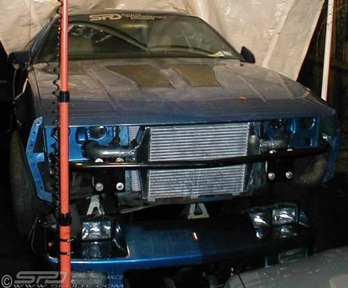
September 23, 2006
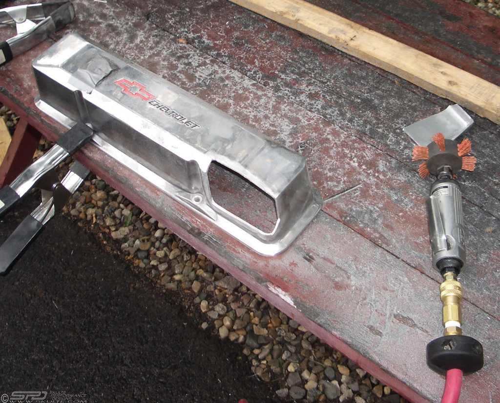
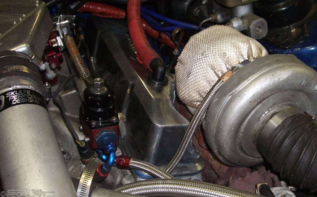
Welding valve cover pockets
Since I built the new engine, there have always been oil leaks coming from the valve covers. These AFR 210 heads are perimiter bolt, while the old L98 had centerbolt valve covers that never leaked. I initially had some gorgeous sheet metal valve covers, but they hit the turbos severely, so they were sold to Rick, for his mean yellow 427 Camaro. I then acquired some solid cast aluminum valve covers from David Tuschoff at Thunder Racing, but they also hit the turbos. The only ones that would clear were the cheapest, flimsiest stamped steel valve covers. Which leak. Even with The Right Stuff RTV that seals anything. I was fed up with the mess, and finally took the die grinder to the cast aluminum valve covers, and cut out sections. Quite a bit was necessary for the drivers side, but the passenger side barely hit. There was a concern about the heat warping the valve covers, but a friend of mine from my days at Mallory (Jeff Diener) suggested welding them in a baking pan of water, to act as a heat sink.
Marking the valve covers:
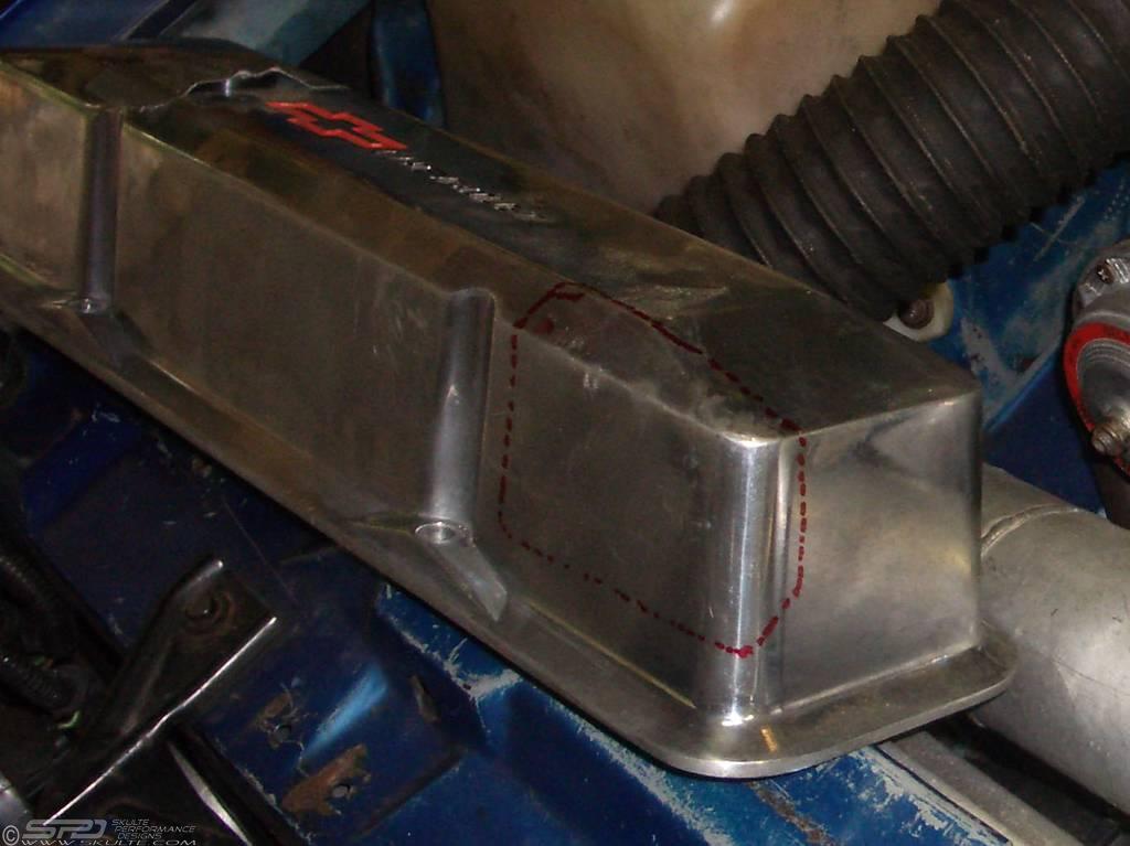
Getting a fresh edge for the TIG welder:
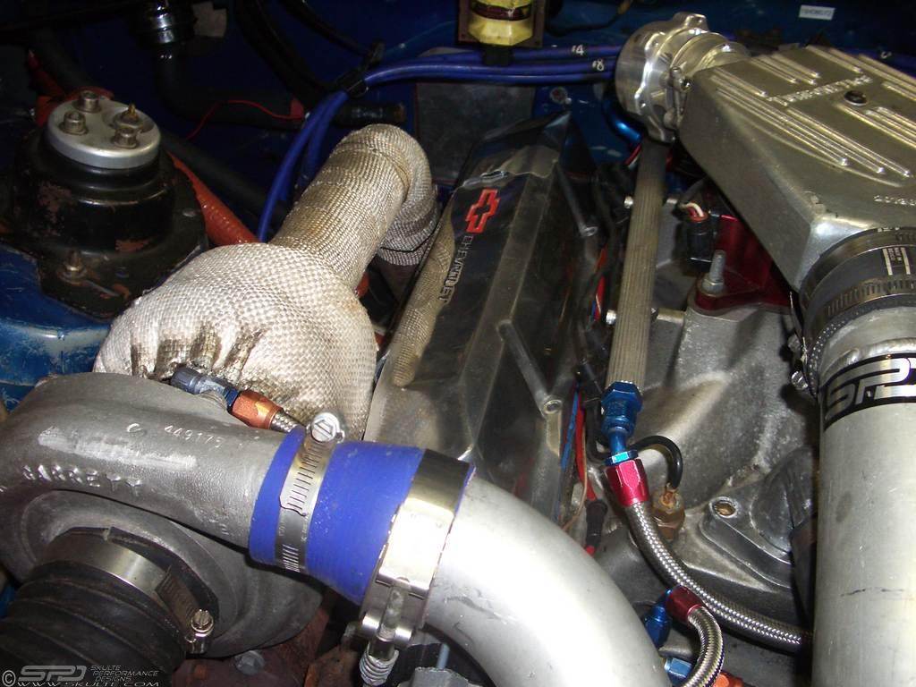
Checking clearance against the passenger turbo:
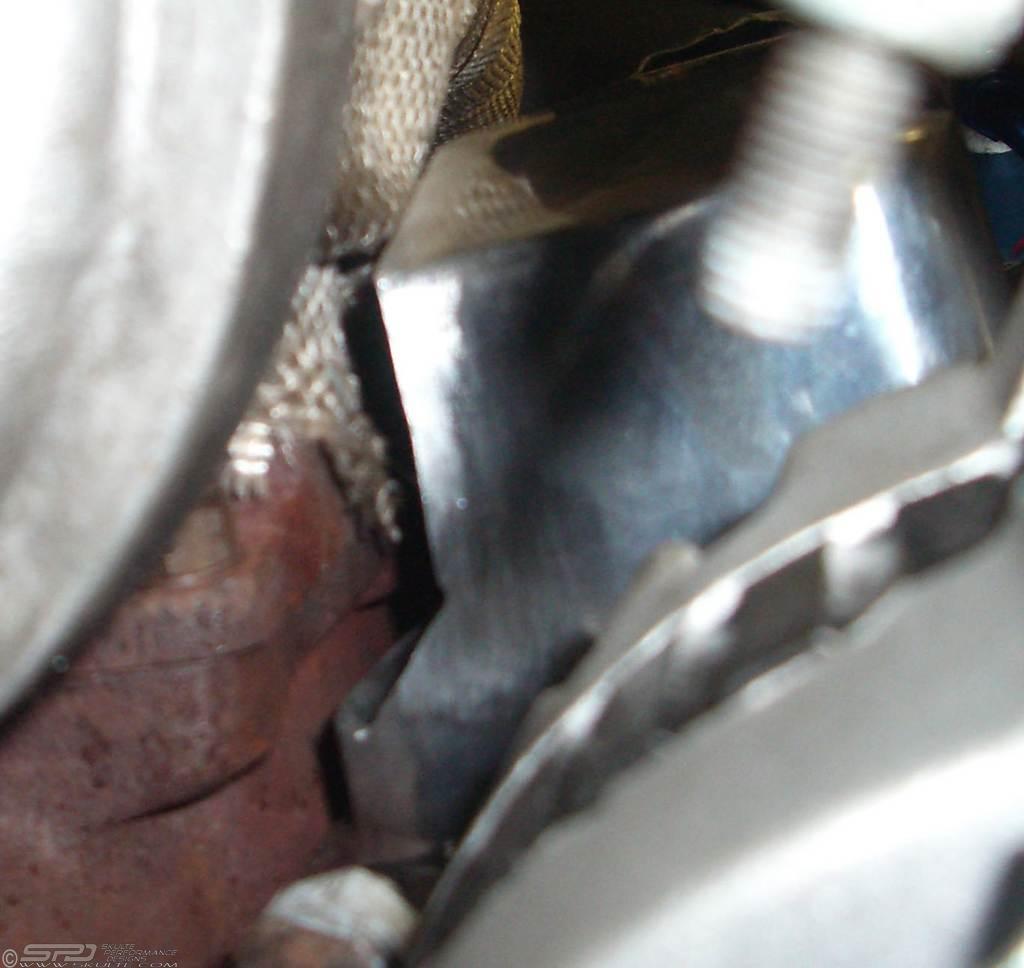
Closeup:
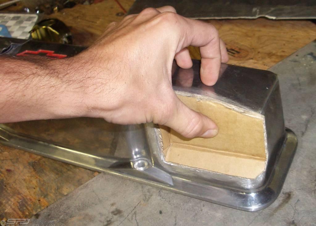
Cardboard Template:
Tacking the piece in place:
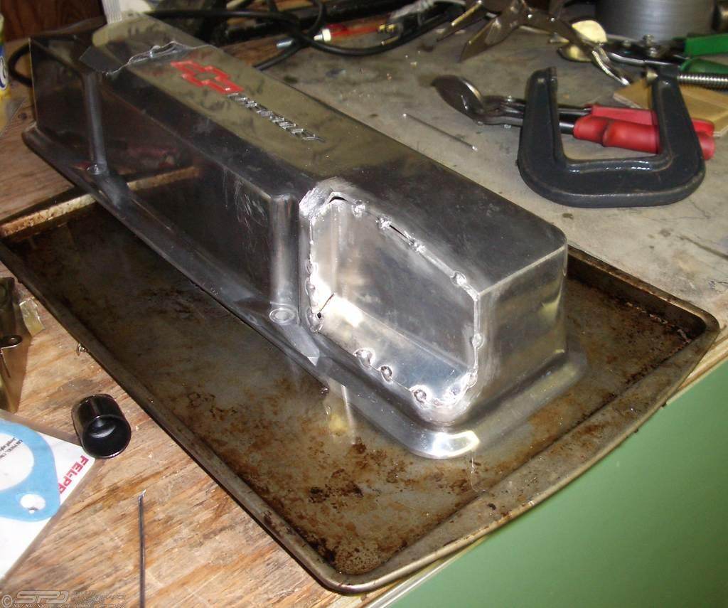
Passenger Side Complete:
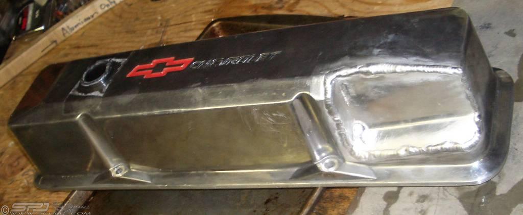
Drivers Side Installed:
Posted by Z28tt at 10:53 PM
July 18, 2006
Mufflers
Installing the NASCAR take-off boom tube side exhaust (previous exhaust was the SLP 3" catback with a single 3" in dual 2.5" out straight through exhaust, they claim is good for 650hp), the Z28tt sounds great at the track. It is a bit loud, and I'd like to keep my neighbor happy, so now I'm on the quest for a decent pair of mufflers. Searching the net, here are some opinions I've found at:
www.gnttype.org
www.turbomustangs.com,
Muffler shootout - http://racetruck.tripod.com/muffler.html
http://www.nsxprime.com/FAQ/Miscellaneous/exhausttheory.htm
Another muffler test - http://www.v6z24.com/howto/mufflerchoice
Part of the noise could also be the open wastegate dump pipes - I may have to look into bringing them into the downpipes as soon as I up the size from the small 2.5" dual downpipes currently on the Z28tt.
I called Dynomax, and according to them, the bullet race mufflers lower the dB by 2-4, while the Ultraflow Welded and Ultraflow SS lower it from 10-12 on the short ones and 12-17dB on the 20" long mufflers. Since muffling depends on the length, dual 3" exhaust with their own mufflers will be quieter than a single 4" exhaust. I followed up by browsing through their catalog. Their 3" in/out Ultra Flow Welded Universal Mufflers all flow 1800 cfm @ 20.3" of water for the straight through (center-center or left-left inlet-outlet) mufflers, which they estimate is good for 818 loss-free horsepower. Changing to a center-left knocks it down to 1300cfm/591hp and a left-right gets it to 1100/500. Their 3-1/2" center muffler is good for 2200 cfm/1000 hp, but I wonder how well it muffles. These are all 4-1/2" x 9-3/4" oval mufflers.
Spoke to Magnaflow, and the tech recommended their 12469 5x8" ovalized 3" dual x-pipe muffler, that's 18" long, which has a roughly 6" cross section in the middle of the x-pipe (http://www.magnaflow.com/02product/shopexd.asp?zone=main&id=476). I wasn't able to get any flow numbers or estimates of how well it quiets things down. They also have 4x9" oval mufflers for more ground clearance, and a 5x11" (pn 12599) dual in/out oval as well.
After reading dozens of threads this morning, speaking to tech support, and thinking things over, it seems like the choices are narrowed down to the Dynomax Ultra Flow, Magnaflow Universal, or Hooker Max Flow. Time to measure under the car to see what needs to fit.
Bullet type mufflers - flow great, but barely muffle
Borla XS - quiet from the tests, but no 3" or larger...
Flowmaster - Terrible flow
Hooker Aerochamber - quietest, higher backpressure
Dynomax Ultraflow - straight through, decent quieting
DNA - Direct Natural Airflow - Race muffler - loud, flows great
Magnaflow - great flowing, quiet, very low backpressure (http://www.turbomustangs.com/smf/index.php?topic=63459)
Hooker Max Flo - quiet at idle, loud at WOT.
Posted by Z28tt at 1:56 PM
June 1, 2006
Deltagate part numbers
Since I melted the back of the Turbonetics Deltagate, I need a new diaphragm and inside cover.
Diaphragm, pn 20113, $27.87msrp
Diaphragm Base Inside Cover, pn 20300 not avail?!!
Diaphragm Outside Cover, 20117, not avail?!!
Posted by Z28tt at 10:48 AM
April 27, 2006
Distributor gear shims
The old HEI distributor has about .040 vertical play, so I'm on a quest to find some shims to take out some of the slop. The existing shim has an OD of .982", and the shaft OD is .425"...
Posted by Z28tt at 4:21 PM
April 5, 2006
Valley drain back testing
Today Mark & I tried a few different oiling tests... First we just spun the oil pump with an old distributor to see how much oil flows through the heads and lifters - not too much with cold 20W50. Next we disconnected the -12 feed, and had that dump right into the valley. Than pan pumped dry quickly, and then started pumping aerated oil spurts. We noticed the oil drained through the Moroso valley screens much faster when the pump was moving, creating suction in the pan. Otherwise it was fairly sluggish, taking a minute or two to drain down, filling the valley with about 1/2" deep oil. Blowby pressure probably does the same thing. Final test was pumping the oil through two -4an lines into to see how much that flows. The oil was already partially aerated, so the dense fluid emptied from the pan fairly quickly. We're just going to put the intake manifold on, and see how much of a difference the .125 restrictors make. If that doesn't help, next step is to remove the valley screens.
Posted by Z28tt at 4:25 PM
April 4, 2006
Measuring the oilpan
We're reassembling the engine tonight, and did a few more measurements on the Canton pan. The side kickouts are about 2.5" deep as measured at the bottom of the pan. The bottom of the windage tray is 3.375". We measured the oil level at 2.5" in the pan, and it came to about 2.75" on the dipstick. The dipstick is notched at 3.625, which corresponds to just above the bottom of the windage tray.
For future - the dipstick is loose, and must be tightened before running the engine.
Posted by Z28tt at 11:56 PM
January 23, 2006
Spal Radiator Fans
Dual Spal Axial Motor Fans
VA18-AP6-41MA Pull
0" static pressure - 2360 cfm each, 21.6 Amps @13VDC
5.17 lbs
1.1" thick at edge of housing
3.39" total thickness at edge of motor
Spec Sheet at http://www.spal-usa.com/fans/automated/tech_sheets/2036-2047.pdf
Posted by Z28tt at 5:01 PM
October 26, 2005
Gearing Spreadsheet
http://www.skulte.com/z28tt/gears.xls
I whipped up a Excel spreadsheet that can help pick your shift points, based on maximizing your HP in the current and the following gears. It's filled with my info, but you can overwrite the cells (in blue) for your cars.
1. Enter Gear Ratios, Tire Diameter, and Rear Ratio (in blue). Current numbers are actuals from the Z28tt.
2. Enter approximate shift points (in blue).
3. Enter Horsepower Numbers on "Matrix" worksheet. Currently they are calculated from a 4th order polynomial that matches the Z28tt power curve from an old dyno run.
4. Play with shift points to max out "AvgHP", which is area under the curve. These are the intersection points of the HP vs MPH curves below. Change the shiftpoints to match the "Shift MPH" on the graph below. You'll see it affects the next gear as well, since that is the starting rpm for the next gear.
First step was to get the gear ratios, shift points, and the following gears starting rpm. That generates the gear drop chart below, and is good for figuring out what speeds are possible in what gears. Next was to get HP in there. I wanted to use a simple calc formula to get "area under the curve", based on my dynochart's polynomial equation, but I couldn't figure out how to make Excel do that, so I had to create a "true/false" matrix, based on whether the rpm is inside the gear's range (start and finish rpm), and only count the true cells in the average. You can overwrite the torque values in blue to get your own dyno curves in there. If you want to use a polynomial function, and just change values A-D, graph the HP as a scatter plot, finish that, and then click on "chart>add trendline" and click on "display formula on chart". You can enter those values into A through D. The worksheet is protected to prevent accidental overtypes.
Later on, I'd like to add a start and finish mph, so you can max out HP for specific straights between corners. This would let you pick rear ratios to optimize specific tracks, since we're not about to change internal gear ratios in the T56. If anyone knows an easier way of doing this, I'm all ears.
Posted by Z28tt at 7:58 AM
Oiling System Tests
My oiling issues first appeared with this new engine. The oil pressure would drop under sustained cornering (big bend at Limerock, the oval at Pocono, etc...). Added a 3 qt Accusump, but that didn't help much.
Oiling system is a wet sump, Melling 155HV
blueprinted pump (Canton), fed through -12's to a CM filter, through the cooler, and into the front of the block (Dart LittleM). All galleys were fed in parallel. I removed the engine, verified pickup clearance at about 3/8", and blocked off the front of the lifter galleys so the mains are fed first. Lifter galleys then get fed from the rear of the block through .1875 orifice plugs.
For my tests, I removed the intake manifold, and had my oil pump primer driven by my drill press head spinning at 590 rpm (1180 engine rpm effectively). There is a lab grade 5" pressure gauge at the oil inlet at the front of the block, and my Autometer gauge at the rear of the block (reads 4 psi low to the same source, but all numbers are corrected below).
Tests using 20W50 oil at 60 degrees air temp.
Test1 - Block off front lifter galleys, no plugs/orifices in rear Front gauge at 30 psi, and rear at 27 psi.
Test2 - Block off lifter galleys completely. Front gauge at 63 psi, rear also at 63.
Test3 - Feed lifters from rear with .1875" orifice plugs. 35 psi front, 27 psi rear
Test4 - Block off passenger lifter galley completely. Drivers has .1875 orifice. Pressure back at 60 psi.
Just realized the oil pump primer may be blocking the oil galley orifice, so I measured w/ the mic, and there is plenty of room in the groove. For kicks - I raised the primer slightly, and pressure jumped to 55 psi. Raised it again, and up to 60 psi. I think it's time to get the old dist, and turn that into a primer. Anyone know what kind of oil flow & pressure hydraulic roller lifters need? The "techs" at CompCams tell me not to restrict it, but can't tell me what sort of flow I need.
I then took an old distributor, bolted down the intake manifold, and ran the pressure tests - 63 up front and rear. I guess the generic $20 primer gave funny data. Anyways, I'll leave the orifices in place for now, and see if the lifters tick. I also considered making an engine run stand that I can rotate to 63 degrees to simulate 2g cornering (not that I come that close), and seeing if the oiling issue is drainback from the heads under hard cornering.
Tangent(tilt degrees) = Simulated G's
Tan(63.4)=2 G's
Posted by Z28tt at 7:50 AM
October 23, 2005
Oiling Systen
Late Model Camaro/Firebird Roadrace Pan (15-246) with 3 trap doors, teflon coated windage tray, full length recovery pouch, 6 qt sump for 7 qt capacity
Canton High Volume Pressure Balanced Oilpump (21-560) - Melling M155HV (4.5gpm@idle, according to Melling)
3/4" pickup, 3/8" above bottom of pan
Oil Pump Bypass Plugged
Canton Remote Oil Filter Boss (22-581) with inlet plugged by -12 O-ring plug
-12 90 deg O-ring hose end, 46" -12 Aeroquip Braided Stainless hose, 12 90 deg O-ring hose end
Canton/Mecca 6" tall billet oil filter (C/M 25-106) with long 8 micron filter element (26-100) and -12 o-ring bottom inlet and side outlet (flows 90 gpm?!!)
-12 o-ring to -12 AN male fitting
-12 straight hose end, hose, 45 deg hose end
-12 to 1/2" NPT male adapter
oil cooler
-12 to 1/2" NPT male adapter
-12 straight hose end, -12 hose (37.5"), -12 45 deg hose end
-12 to 1/2" NPT 45 deg adapter (with -4an welded on for turbo oil feeds)
Engine Block feed in front
Blocked off lifter galleys
Lifter galleys fed from rear after mains through .1875" orifice plugs
3qt Canton Accusump (24-006) with manual ball valve inside cabin fed through -10 firewall connector and -10 hose to 1/2" NPT feed at top rear of block
Posted by Z28tt at 7:26 PM
May 1, 2004
Engine Specs
Bottom End:
Pistons: JE Pistons Extreme Duty Inverted Dome
Part # 206371
.280 Top Land (.064 Groove)
.182 2nd Land (.064 Groove)
.095 Bottom Land (.218 Groove)
494 Grams
Double Pin Oilers
Accumulator Groove
Oil Rail Support (RA 4125)
.0005 Pin Fit
Double Spiro Locs (5 grams)
2618 Forging
4.1215 Bore
Inverted Dome, .230" Deep, 28cc
8.25:1 Compression Ratio
1.151 Compression Height
Swain Tech Thermal Barrier Coat Dome & Poly Moly Coat Skirt
Wrist Pin: JE 927-2950-18-52S
52100 Series Steel
.927" x 2.950" x .180" Wall
Casidiam DLC Coated (+.00016 on OD)
162 grams
Rings:
JE100F8-4125-5 (Total Seal)
Top: 1/16" Plasma Moly Ductile Iron Barrel Back Cut
2nd: 1/16"Cast Iron Phosphate Taper Face
Oil: 3/16", Carbon Steel Chrome Plated Std. Tension (8 S34125-0-316CUS)
.022/.023 Top Ring End Gap
.014/.015 2nd Ring End Gap
58 Grams (From Balance Card)
Crank: Callies Dragonslayer
3.750" Stroke
2.4486" Main Journal
2.0995" Rod Journal
Block: Dart Little M Block
205 lbs
Deck Height: 9.025"
Bore: 4.1225"
Main Bearing: 2.45 or 2.65
Camshaft Dia: 2"
Deck Thickness Min: .675
Deck Height (measured on granite surface plate): Pass 9.0291" (1.3206+7.7085)
Drivers 9.0259" (1.3206+7.7053)
Main Bearings: Clevite 77 Performance MS-909 H
Hot Honed to 4.1215" bore at Billy The Kid's in Torrington, CT
Rods: Eagle H-Beam
6" Long
ARP L19 Bolts
2.250" Dia. Big End
.9277 +- .0003 Smal End
All w/in 1 gram of 650g
180 small end
750hp @ 7000-7500 rpm tension load
Camshaft: Comp Cams Custom Grind
Grind: CS 3316/3315 HR 113.0
3316 Intake Lobe, 3315 Exhaust Lobe, 265-400 Core, Std Journals, PN 12-000-8
Serial No. Y 3754
Lobe Lift: .347/.340
Lift @ .050 (1.5 Rockers) .520 / .510
Lift @ .050 (1.6 Rockers) .555 / .544
113 Lobe Separation Angle
Gross Lift: .520/.510
Duration @ .006: 288/281
Valve Timing .050 (Installed at 109 deg Intake Centerline)
Intake - Open 9 BTDC, Close 47 ABDC
Exhaust - Open 52 BBDC, Close 2 ATDC
Cam Installed on 108.5 Centerline, (4.5 Deg Adv)
Balance: At Billy, The Kid's
3.750 Callies, Internally Nutral Balance
RodRot 460
RodRot 460
RodBrg 44.5
RodBrg 44.5
Oil Allowance 4
Piston + Pin 494+162
Locks 5
Rings 58
Rod Recip 185
V8 BobWgt 1917-384
50% Recip 100% Rot
Piston Weights
A 494.2g
B 495.7g
C 494.9G
D 494.0g
E 495.2g
F 495.6g
G 494.5g
H 493.7g
Wrist Pin Measured Diameters
1 .9272
2 .9272-3
3 .9272
4 .9271-2
5 .9271-2
6 .9271-3
7 .9272
8 .9271-2
Piston Diameter (Measured .500" from bottom of piston, 90 deg from wrist pin
Clearance Set To .0045"
A 4.1174 (4.1150 @ oil ring)
B 4.1172 (4.1147)
C 4.1172 (4.1150)
D 4.1173
E 4.1175
F 4.1175
G 4.1174
H 4.1172
Ring Gaps (Top-2nd)
1. 22-19 2. 20-16
3. 21-15 4. 21-16
5. 20-18 6. 25-17
7. 21-13 8. 21-15
Main Bearing Clearance
Quick Plastigage Check
#1 .0028 (<.003 line)
#2 .003
#3 .0029 (<.003 line)
#4 >.003
#5 .003
Crank Thrust Movement: .005"
Top End:
Heads:
Airflow Research 210cc (Part # 1050)
Race Ready CNC Port
76cc Chambers
8015 Springs
Titanium retainers
Angle Plug
Std. SBC Exhaust Ports
Valve Springs
AFR 8015 Orange w/ Blue Stripe
140/350 lb/in
.560 lift (Hyd. Roller)
1.79"
1.090" coil bind
Intake Valve = 2.080" Dia. 125.8g RevCL 1646
Exhaust Valve = 1.600" Dia. 98.3g RevCL 1632
Titanium Retainers = 17.2g
Keepers 5.7g
Valve Stem Heights (I/E)
1 .863/.887 (.855 w/ Intake Retainer)
3 .862/.882 (replaced defective intake keeper)
5 .875/.892
7 .852/.863
2 .881/.892
4 .882/.891
6 .877/.868
8 .882/.890
AFR Hyrda Rev Kit for aftermarket lifters
CompCams Retrofit hydraulic Roller Lifters (Part # 885-16)
Comp Cams Pro Magnum 1.6 Roller Rockers on 7/16" Studs
ARP 190,000 PSI 7/16" Dia. Head Studs
Timing Chain: Cloyes Hex-A-Just 9-3100A Roler Timing Set
Timing Cover: Cloyes 2 piece Aluminum
Felpro Loc-Wire Head Gasket Set (Part # 1045, .039" Thick)
Harmonic Damper: ATI 7" OD 3 Ring Aluminum Nuetral Balance
Crank 1.2470", Hub 1.2450", Honed up to 1.2460" for .001 Press Fit
Accel Pro-Ram Intake Manifold
Turbonetics Deltagate Wastegates
Turbos: Twin TO4E, 40 Series, O Trim, .58ar
Force-efi 1000 cfm 4 barrel throttlebody
Siemens 3102 55 lb low impedence injectors
Walbro GSS307 fuel pump
Aeromotive Fuel Pressure Regulator
Water Pump:
Stewart Stage II
Long, 87-up
3/4" bearing, 5/8" Shaft
High Flow
CCW Rotation (Reverse)
180 deg Thermostat
Thermostat House/Neck: 2 piece with o-ring (Felpro 35261 or 10-1229 for Buick, Olds, Pontiact 4 112 Engine 1982-1994)
Pilot Bearing - Competition Products Chevy 41110 1.093" OD x .72".3
Posted by Z28tt at 3:58 PM